This article is written in the form of course which will contain different chapters to get overview of Wiring harness development in CHS (Capital Logic and XC).At the end of this course ,you will be able to design the schematics in capital logic tool.
This course will give you practical exposure of wiring harness and technical understanding of different systems.
Chapter 1:
CHS: Introduction of Capital Logic :
- Capital CHS comes with different Software package which are essential for wiring harness creation.
- First is Capital Logic which helps in schematic creation , simulation and report generation.
- Second is Capital XC which helps in 2D drawing creation , layout creation which used to create the Form board creation .It also helps to create the BOM (Bill of Material).
- Third is Capital Symbol which helps to manage the symbol (graphic creation) for creating the schematics.
- Last but not Least Capital Library which used to mange database of component.
- Capital Logic is very powerful tool which helps to create wiring harness design in digital environment and helps to implement the Logical design to physical wiring harness.
- Capital logic is a schematic design tool. once you created schematics, to create 2D drawing CHS comes with Capital XC Package which coverts the Logical design to 2D drawing.
- Capital Logic provide the Simulation Analysis as well which helps in validation of circuits . Example: Voltage drop etc.
Capital Launcher GUI (Graphical User Interface CHS)
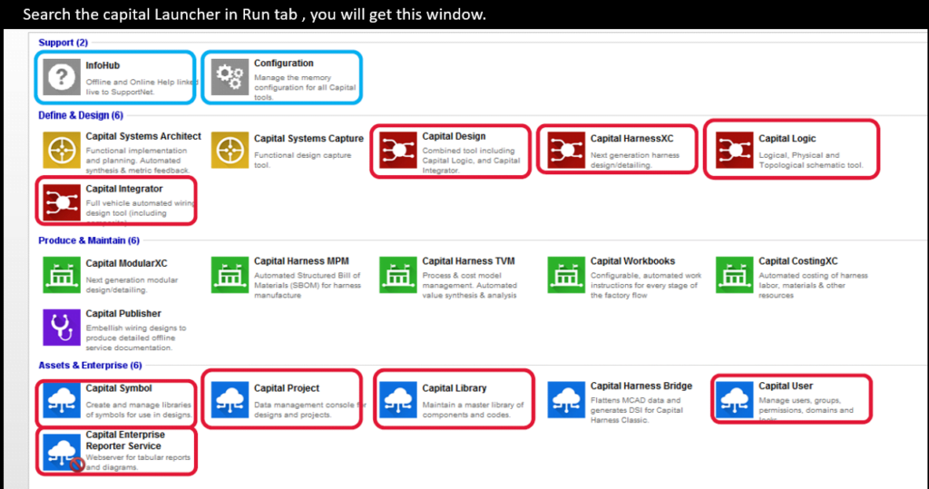
When you run capital launcher on your system, A GUI will pop up on your computer screen which asks you to select the different package of CHS software.
As you can see below we have different package suits like :
- Capital Design
- Capital Harness XC
- Capital Logic
- Capital Integrator
Under Assets & Enterprise , we have Library handling like Capital Symbol, Capital Project, Capital Library ,Capital User and so on.
However, we will use two packages very frequently. First is Capital Logic and second one is Capital XC.
Examples of Logical Diagrams in CHS
Before jumping to the Capital logic Tool , we try to understand that what are basic components of any schematics and how read the schematics in Capital Logic.
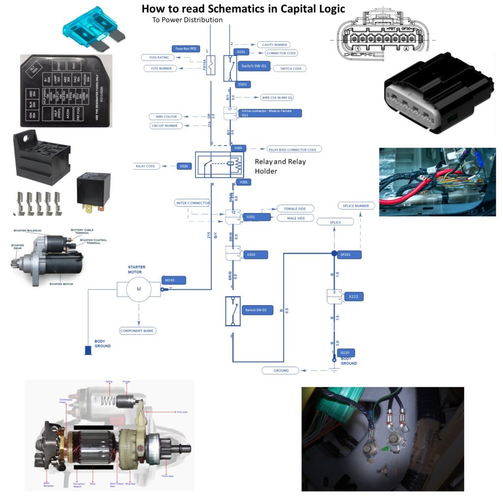
As you can see in the above schematic , we have divide the our schematic into three diifirent section
- First section which is Power distribution comes in upper.
- Second section which have components comes in middle.
- In last (or) down side we place our ground distribution.
We have shown the essentials information of Schematic design in above schematics which are mentioned below.
- Fuse Number : F6: It denotes Fuse number of the particular fuse which is printed on the fuse box cover as well. It helps to identify the particular Fuse during serviceability.
- Fuse rating:15A: This values denotes about the protection given for particular wire based on continuous current.
- Wire Color (GR): As its name suggests this represents color of wire which is green. It plays very vital role in serviceability. We will discuss in detail when we will discuss the POKA-Yoke Issue.
- Circuit Number:214:-Circuit number is nothing but it gives the identification to the particular wire to identify the To and From component.
- Relay code:G520: Relay code is the name of relay which is used for switching the circuit.
- Relay Base Connector :H201: This is relay holder in which relay going to fit (or) inserted.
- Inline connector:X201:Inline connector are those connector which are used make the connection from one section of car to other section of car. For Ex: Engine room Harness need the connection from Passenger compartment ,in this case we need the Inline connector as we have divided our harness in two different harness.
- Component Name: Starter Motor: It denotes name of the component like Relay, starter motor, switch and so on…
- Ground: There are different types of ground in automobile. One is ECU ground which is directly given to ECU as Active Low. Second type of ground is Body ground which generally connected to Chassis (or) body of the vehicle.
- Splice (SP 201): Splice are used to give the Joint and to take the same signal/energy from that point.
Essential Requirement before starting with Capital Logic and XC:
As we have seen many parameter’s above which are used in schematics.
- we make to sure that all the parameter’s name should be unique. Circuit names , connectors name ,splice name, all references names given to component and so on should be unique.
- Wire Size with accurate information of Terminal, wire seal and Dummy plug need to be documented in Library.
- All symbols and graphic of components to be documented in capital which need to be taken care by Librarian.
Capital-Library and Symbol:
Capital Library:
- Capital Library is database of the components which are used in different projects.
- Capital Library is used to manage Supplier and customer part number ,symbols, views and all other details of the components.
Capital Symbol:
Devices can be represented either by rectangular block having pins ,or by using a predefined symbol.
symbols are predefined graphical representation of devices and are maintained using capital symbol.
There are many different types symbols
- Comment
- Device
- Ground
- Border
- Backshell
Symbols are placed by double clicking on required symbol.
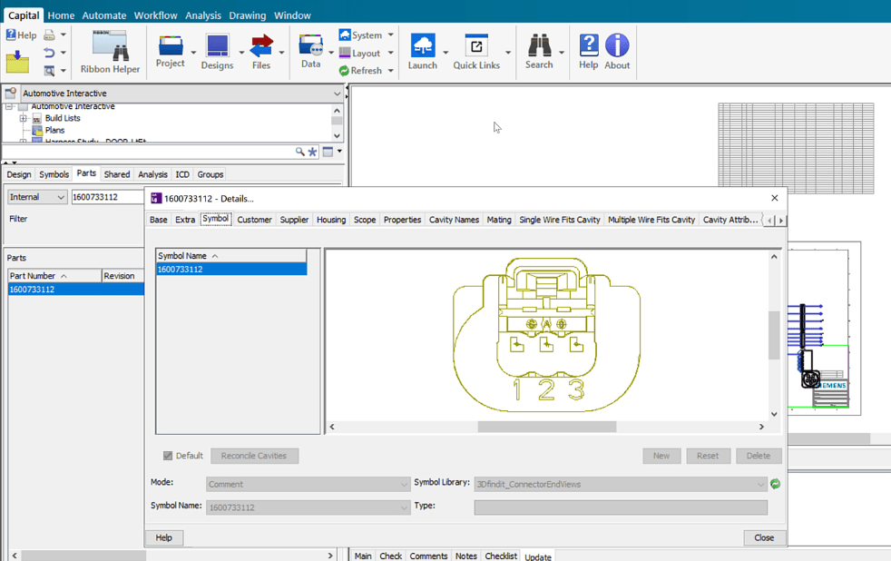
Once device (or) ground symbol is added into a diagram, a name is automatically applied to symbol. You can change the name of device according to your requirement.
Creating New projects in Capital Logic:
Once you open the Capital Logic suites, you will get the GUI something like mentioned below:
We will try to understand graphical user interface of Capital step by step.
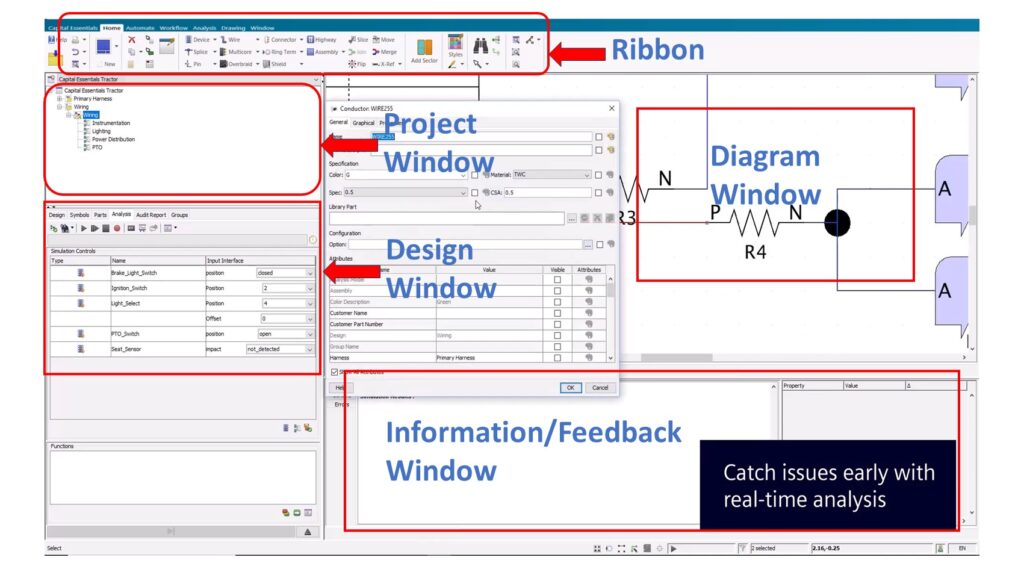
Capital Logic GUI contains total five windows.
1.Ribbon bar: Ribbon bar contains all the options in Home Tab which are used to create wiring harness schematics.
you will find below mentioned options under ribbon bar
- Device
- Splice
- Pin
- Wire
- Multicore
- Overbraid
- Connector
- Ring Terminal
- Shield
- Move
- Merge
- Flip
- X ref
2.Project Window: Project window gives overview of different projects created for different cars.
All created projects will come under this Tab. If you have created New Project ,it will reflect here.
you can create build list in this window which will helpful for synchronization between Capital Logic and Capital XC.we will see this topic in coming chapters.
3. Design Window :Design window will give you overview of components used in projects.
It consists below mentioned Tab:
1.Design
2.Symbol
3.Parts
4.Shared
5.Analysis
We will discuss all these Tabs in details.
4.Information (or) Feedback Window: As its name suggests, It gives the information about all activity which we perform in Diagram window.
5.Diagram Window: This is your workspace where you create your schematic with help of all the options (Ribbon Tool Bar) which we discussed above.
We have divided this course in different chapters. You can find the list of content which are going to cover in this whole course.
Table of contents:
- Introduction
- Capital Launcher GUI (Graphical User Interface)
- Examples of Logical Diagrams
- Essential Requirement before starting with Capital Logic and XC
- Capital-Library and Symbol
- Creating New projects in Capital Logic
- Opening the Projects
- Naming Conventions/Defaults Name
- How to Manage Variants/options in Capital Logic
- Creating Designs
- Different Borders and Style sets
- How to add Devices in Capital Logic
- Parametric symbols
- Adding connectors
- Adding Part Numbers
- How to manage Inline Connectors
- How to use Ground terminals
- Managing Wires in Capital Logic (Regular Wires, Twisted Wires, Shielded wires- Cables)
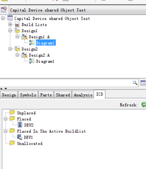
- Shared Objects in CHS
- Shared Objects Pin Creation
- Build List
- Design Management (importing and exporting projects)
- Printing designs
- Design Validation (DRC)
- Simulating the Circuit
- Generating reports
- How to Take .XML file and Integrate it with 3D design (NX/Pro-E/Catia)
- Useful Shortcut Keys
You can check out the video on Basics of Wiring Harness.
You can read the article on basic understanding of Wiring Harness.
Hi. I am a 65 year old man who works as an offsite consultant electrical designer, with primarily a background in Creo. I have used VeSys, but not CHS. VeSys is basically Capital Logic and Capital Harness XC, on a scaled down version. I created the symbols, and I created the library Components. I was able to create the wiring diagram, and then I was able to synchronize the wires/cables/components over to the formboard/harness drawing. I was learning the software along with NX and everything was working ok, except for a few items. I would really hope that you could provide some guidance for these items. First, I could not figure out how to set up two different views of the connectors, and use the Styling Editor to set it up to swap one connector view with another one on the drawing. Second, I could not figure out how to create properties in the library components, and have those properties transfer over to NX when I created the PLMXML file. I know you can do it automatically by setting up a Bridge, but I could not figure out how to get the Bridge to work. I was told by Siemens that NX 12, which I was using, did not have updated JAVA files, to allow the Bridge to work. So I tried to transfer the information over manually with a PLMXML file. The properties like Name, etc., did not come into NX. Also, I could not get NX to AutoAssign the Connectors. The biggest struggle I had with VeSys was correctly understanding how to use the Styling Editor to create the proper settings to make the library work properly. Thank you for the work you have provided thus far, and I look forward to future videos/information…thx…Mike
Hi, I’ve used CHS Logic, Integrator and XC for harness design but there are a few things that I quite don’t understand yet. All the options on de Design on the Design window to filter, and search. What does a buld list is and if that has something to do with configurations and levels. And also Share objects. I know That makes the object (same object) usable on any diagram or design but sometimes I have trouble adding, deleting and merging and I haven´t found the root cause of that. I might be doing something wrong.
I hope you could talk about these characteristics in a video.
Thanks in advance!