Introduction of connector
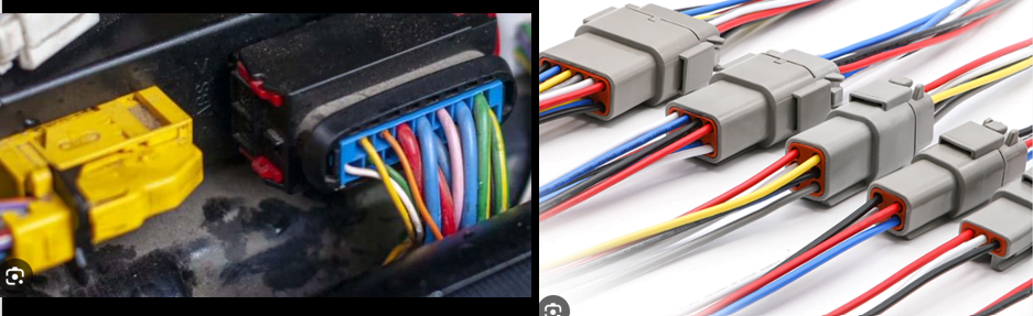
What is connector?: Connector is a device which is used to create the bridge from one end (of Harness) to other end (of device/connector).
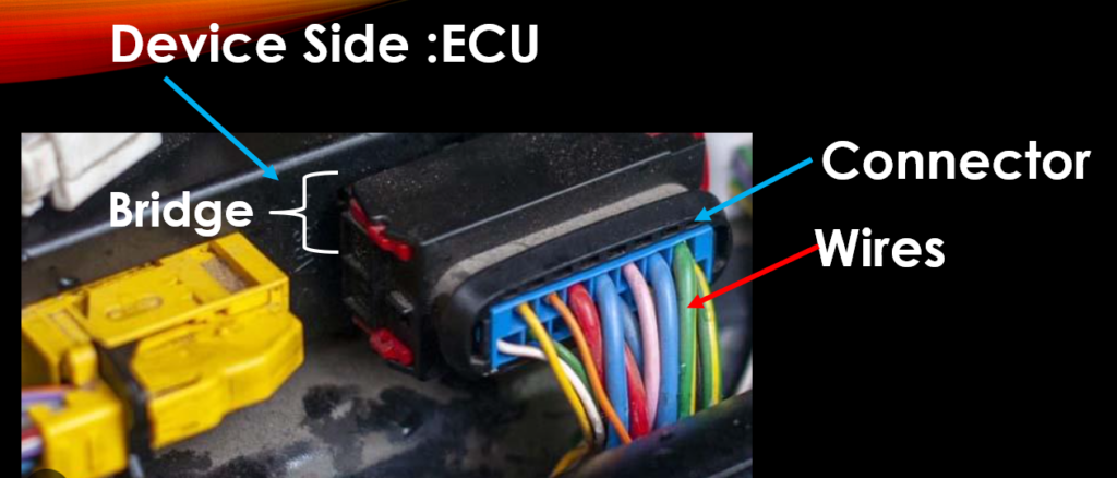
As you see in above picture, One side we have Device (which can be anything like sensor etc.) which need energy transfer from one end to other end (which can be Fuse box, Ground or any other device) .
In short, Connector is a device which transfer energy from one end to other end.
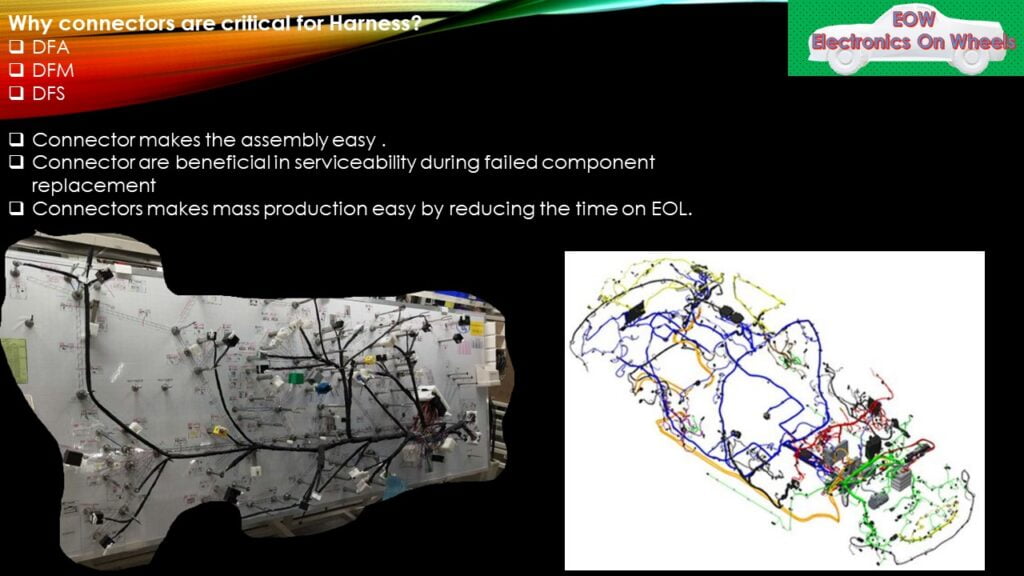
Why connectors are critical for Wiring Harness?
Connectors plays very important in Wiring harness design. Connectors are useful when it comes to DFA,DFM and DFS. We will try understand these terminology to get the criticality of connectors in wiring harness.
DFA: Design for Assembly: As its name suggests this particular terms relates for Inline connector during assembly of harness . Let me take one example of car.
As you are aware that in Car, our harnesses are divided in sub small harness like Body harness, Dash Harness, Engine Harness, Door Harness etc. and Body harness is connected to DASH harness through Inline Connector.
But suppose if you do not have Inline connector between Body Harness and DASH Harness, do not you think that it would be very difficult to assemble the complete harness (Body +DASH) for operator on production line. Indeed , It will be very complex for operator to lay down the Harness in whole Vehicle as single .
That’s one why connectors plays very important role in wiring harness.
DFM: Design for Manufacturability:- Similarly its easy to manufacture the small Wiring Harness if you are using the connectors.
DFS: Design for Serviceability: Design for service comes into picture after market. Example: Once vehicle is sold and after running for good number of years ,your vehicle Headlight is not working and you go to service center . Can you imagine if you have your harness in single piece, how much effort a servicemen need to put to diagnose one fault. Servicemen need to take out whole harness to diagnose one issue.
These are few reasons which makes connector very critical in wiring harness.
Connector components:
Non Waterproof connector: Connector Base structure of Non Water proof connector: Non water proof connectors are used in dry zone area of vehicle like passenger compartment ,cockpit area etc…
- The connecting latch is shielded by the bridge construction.
- The guide prevent tilting when connecting the connectors.
- Every angle has a large chamfer and diameter.
- The polarisation structure ensures that the connector and device are correctly matched.
- A well-designed ergonomic structure supports the shifting of connectors.
- Excellent visual and auditory input.
- To ensure that the terminal is on the same plane, adjust the blank position.
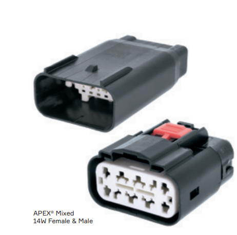
Waterproof connector: Waterproof connectors are used in wet area of vehicle like Bumper area , Chassis etc…
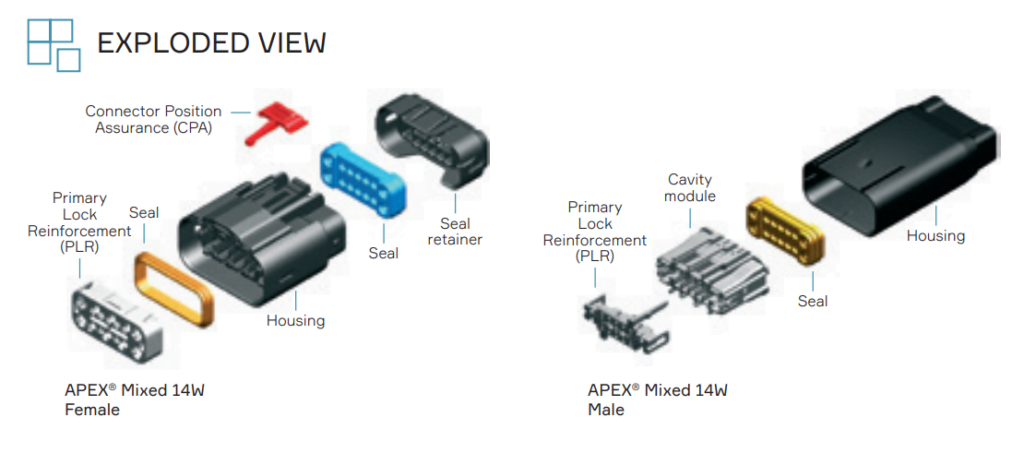
1.ISL (Independent Secondary Lock):It is used for locking and fixing the terminal which is independent component out of the connector housing.
2.TPA (Terminal Position Assurance):TPA is also the component which place the terminals in its right position but its different from ISL and its part of connector.
3.Latch: It is the lock structure between two mating connectors. In general, we call it primary lock of the connector.
4.CPA (Connector position Assurance):Just like TPA, CPA assure the two connectors connect and fix in the right position. CPA is secondary lock for connectors. CPA is not necessary to be applied in all environments. Usually latch is adequate to assure the connect well, but if vibration is frequent ,we suggest to use CPA for doubling guarantee. Ex: connectors in Engine room.
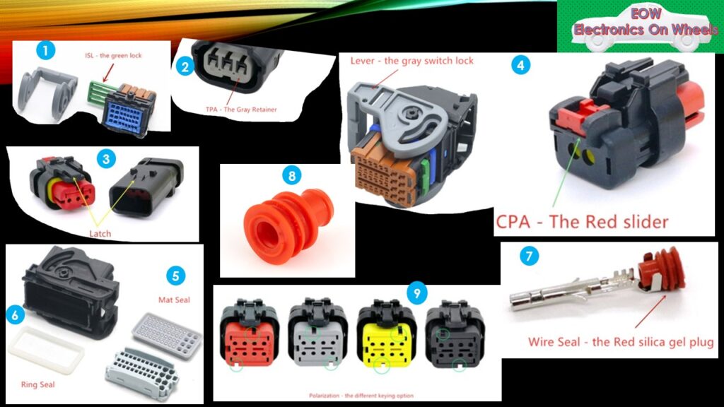
5.Mat Seal: Play a role of waterproof protection in the connector housing.
6.Ring Seal: It is seated between female and male connector for waterproof protection.
7.Wire Seal: crimped with wire in the end of terminals for waterproof protection
8.Plug: Insert it in the unoccupied hole of connector for waterproof protection.
9.Polarization options: we also call it coding .It is a fool-proofing design and different polarization has different color.
10.Terminal:As we all are aware that terminal is the conductor through which current/energy flows from male to female connector.
Specifications the connector:
Mechanical Specifications:
Contact retention force:
This force holds the terminal in place and controls how hard you must pull on it to remove it from the housing.
Contact insertion force
is the physical force needed to insert a terminal into housing; ideally, connectors have minimal insertion force and maximum retention in the housing. By doing this, terminal back out is avoided.
Wire Pull Out force:
The force needed to detach a wire from a termination is known as the “wire pull out force.” In order to maximise the wire pull-out force, terminals are crimped.
Mating Force:
The amount of force needed to connect two terminals is known as the “mating force.”
A mating force is the force needed to separate two terminals.
Normal force,
also known as contact force at the electrical contact point, is the pressure delivered perpendicular to the terminal. When applied correctly, this force ensures that corrosive gases do not enter the contact area and harm the electrical circuit.
Durability
is the amount of mating and unmating a terminal can withstand before performance starts to suffer.
Electrical Specifications:
Working voltage:
Usually indicated as voltage in most specifications, working voltage is the connector’s regular maximum operational voltage.
Dielectric withstanding Voltage:
The greatest voltage that an insulator can withstand and still function at is known as the dielectric withstanding voltage. Overdoing this voltage level is likely to result in application failures.
Contact Resistance:
The maximal resistance provided by the contact area when the connector is mated is known as contact resistance.
Insulation resistance
is a measure of how well a connector’s housing, contact, and general design withstand arcing.
The destructive spark that results from resistance-induced buildup of excess current is called an arc.
Connector Selection Factors:
Electrical Factor: Current requirements: high current, low current, signal level;
Steady state, cyclic, transient.
They determine the type of terminal/size of contact segment/plating (0.64mm to 8.0mm pin and male terminal).
Wire diameter/insulation requirements: voltage drop and/or corrosion resistance, which determine the center distance of the connector.
Location/Environment:
Temperature: Engine compartment – sealed, ambient temperature >105℃; vibration, fluid compatibility, passenger compartment – unsealed, ambient temperature <85℃.
Sealing: Potential for high pressure jet/splash, potential for immersion, humidity; fluid type, sealed or not for device connectors.
Standard:
Standards: Customer Standards
Institutional Standards
Domestic Standards
International Standards
Connector performance test requirements are included in system-level specifications. For GM, Ford and Chrysler are usually USCAR specifications, that is, engine-related applications have relatively high vibration requirements. Other OEMs generally have their own standards (similar to USCAR). What’s more, equipment-side suppliers are responsible for the performance of mating-side connectors.
Physical factors:
Size, number of circuits, mating position, wire harness docking or equipment connection, mechanical main features: levers, bolts; manual docking capability; multiple types of connectors for high input/output applications.
Assembly:
Wire Harness: Insertion force of connector
Visual, audible and tactile operational feedback for users
Customer Preference:
Preferred product strategy: Reduce cost of connector systems with different methods:
Ford: Design competition for door connectors.
Ford: Prefer terminal design/supplier (focus on contact interface).
General: Prefer the terminal design (focus on the hole position of the connector).
Chrysler: Strategies for favoring terminal/plastic Part suppliers
Factors to be accounted during connector selection: Summary
- Load Characteristics
- Wire Size
- No. of pole requirement
- Environmental characteristics
- Vibration levels
- Serviceability
- Accessibility
- Application constrains
- Packaging
- Location
- Cost
vAvailability
Different Standards:USCAR-2-6, QC/T1067-2017 and GMW3191-2012
I will give you overview of few points for QC/T1067-2017.
QC/T-1067 Temperature Classification:
| Class | Ambient Operating Temperature | Typical Installation Position |
| A | -40~85℃ | Passenger compartment (Not recommended) |
| B | -40~100℃ | Passenger compartment |
| C | -40~125℃ | On engine |
| D | -40~150℃ | On engine (hot locations) |
| E | -40~175℃ and above | Negotiate |
QC/T-1067 Vibration Classification:
| Class | Typical Installation Position |
| V1 | On elastic parts of the body but not to the engine |
| V2 | On engine but not to heavily vibrating parts |
| V3 | Components subject to serve vibration |
| V4 | Components subject to extreme vibration |
| V5 | On Wheel |
QC/T-1067 Sealing Classification:
| Class | Description | Typical Installation Position |
| S1 | Unsealed | Passenger compartment or trunk |
| S2 | Sealed | Exposed areas |
| S3 | Sealed (with high pressure spray) | Exposed areas (with high pressure spray) |
Practical examples of selecting connector:
Based on application
• Exterior of the car (outside the cabin: Fender harness)
• Inside the engine compartment (Engine wiring Harness)
• Inside the passenger compartment (IP wiring , door wiring, roof wiring )
• Safety applications (Airbag)
• OBD connector
Based on Electrical Parameter
• Contact resistance
• Wire cross section
• EMI connectors
Based on Packaging location
Packaging location
• Parking provision
• Requirement of cross section
• Ergonomics
We will provide detailed explanation of all the above factors in upcoming article. If you like the article Please leave the comment.
Types of connectors:
Low power connectors
High Power connectors
PCB Mountable connectors
Interconnection connectors
Waterproof connectors
Non water proof connectors
Connectors with Primary Lock
Connectors with primary and secondary lock
Hybrid connectors (Connectors having with different wire CSA: terminals of low and high current rating in single connector)
You can check out the video on Basics of Wiring Harness.
You can read the article on basic understanding of Wiring Harness and tools used to create Schematics.